Working with Resistors
Resistors are the most common component in electronics. Every circuit has them. They limit current, divide voltage, pull signals high or low, and protect components from burning out. Once you understand them, a huge chunk of circuit design starts to make sense.
What a Resistor Actually Does
A resistor opposes the flow of electrical current. The higher the resistance (measured in ohms, Ω), the less current flows for a given voltage. That's it. One job, done extremely reliably.
The colored bands tell you the resistor's value. It looks intimidating at first, but there's a simple pattern to it.
Reading the Color Code
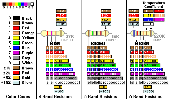
Most resistors you'll encounter have 4 bands. The first two bands are digits, the third is a multiplier, and the fourth is tolerance (how close to the stated value it actually is).
| Color | Digit | Multiplier |
|---|---|---|
| Black | 0 | ×1 |
| Brown | 1 | ×10 |
| Red | 2 | ×100 |
| Orange | 3 | ×1,000 |
| Yellow | 4 | ×10,000 |
| Green | 5 | ×100,000 |
| Blue | 6 | ×1,000,000 |
| Violet | 7 | — |
| Grey | 8 | — |
| White | 9 | — |
| Gold | — | ×0.1 |
| Silver | — | ×0.01 |
Example: Brown, Black, Red, Gold = 1, 0, ×100, ±5% = 1,000Ω (1kΩ), 5% tolerance.
A trick I use: Bad Beer Rots Our Young Guts But Vodka Goes Well — Black, Brown, Red, Orange, Yellow, Green, Blue, Violet, Grey, White.
Calculating the Right Resistor Value
The formula you'll use over and over is derived from Ohm's Law:
R = (Vsupply - Vforward) / IdesiredFor an LED on a 5V supply:
Vsupply= 5VVforward= 2V (typical red LED forward voltage)Idesired= 0.02A (20mA, a safe operating current)
R = (5 - 2) / 0.02 = 3 / 0.02 = 150ΩThe closest standard value is 150Ω or 220Ω (rounding up is safer — a little less current never hurts an LED).
Series vs Parallel Resistors
Series — resistors add up:
R_total = R1 + R2 + R3[5V] ──[100Ω]──[220Ω]──[LED]──[GND]
R_total = 320ΩParallel — the total is less than the smallest:
1/R_total = 1/R1 + 1/R2Two 1kΩ resistors in parallel = 500Ω. Useful when you need a non-standard value and only have standard ones.
Pull-Up and Pull-Down Resistors
This tripped me up for a long time. When a microcontroller pin is not connected to anything, it floats — it reads random values. A pull-up or pull-down resistor fixes that by giving the pin a default state.
Pull-up (pin defaults HIGH):          Pull-down (pin defaults LOW):

[3.3V]──[10kΩ]──[Signal pin]          [Signal pin]──[10kΩ]──[GND]
                    |                        |
               [Button]──[GND]          [Button]──[3.3V]
When the button is pressed in the pull-up setup, the pin reads LOW (0). Release it and the 10kΩ pulls it back to HIGH (1). The ESP32 has built-in pull-ups you can enable in code with pinMode(pin, INPUT_PULLUP), so you often don't need an external resistor.
Power Rating
Resistors have a maximum power they can handle before overheating. The standard through-hole resistors in hobby kits are 1/4 watt (0.25W). Use the power formula to check:
P = I² × R or P = V² / RIf you're pushing 100mA through a 100Ω resistor:
P = (0.1)² × 100 = 1WThat's 4× the limit of a 1/4W resistor — it will get hot and fail. You'd need a 1W or 2W resistor for that application, or redesign the circuit to reduce current.
Identifying a Resistor with a Multimeter
If the color bands are worn or ambiguous, just measure it. Set the multimeter to resistance (Ω), touch the probes to each leg, and read the value. Polarity doesn't matter — resistors work in both directions.

One thing to watch: if the resistor is in a circuit, remove it before measuring. Current from other components will give you a false reading.
Common Resistor Values to Stock
If you're building a kit, these values cover 90% of what you'll encounter:
100Ω   220Ω   330Ω   470Ω
1kΩ    2.2kΩ  4.7kΩ  10kΩ
22kΩ   47kΩ   100kΩ
Buy a 500-piece assortment from AliExpress for ~$5 and you'll be set for years.
Summary
Resistors are simple but they show up everywhere. Knowing how to read the color code, calculate the right value for LEDs, and understand pull-up/pull-down behavior will make you dramatically better at reading and building circuits. Once these become second nature, every schematic you look at starts to make sense.
Next up: capacitors — the component that stores charge and filters noise out of your power supply.